![]()
|
|
|
|
|
|
|
Last update: 08/03/2005 |
|
|
|||||||||||||||||||||||||||||||||||||||||||||||||||||||||||||||
|
|
|
|
|||||||||||||||||||||||||||||||||||||||||||||||||||||||||||||||
|
|
HO2S MONITOR The HO2S sensors must be tested thoroughly because they are at the heart of the Fuel and Catalyst monitors. The operation of the Emissions control in OBD depends on the sensors being at proper operating temperature. Both the catalysts and the HO2S sensors need to be at several hundred degrees C before they are working efficiently, so the latter have heaters built in to get them up to operating temperature as soon as possible. Because the HO2S sensors need to operate at near stoichometry they cannot be used when rich fuel/air mixtures are needed and so:
The HO2S sensors are numbered so that the upstream sensor 1 is always on the Bank which contains Cylinder # One. The down stream sensor is numbered 2. Hence the DOHC engine designs contain the HO2S sensors 11 (forward of the Catalyst) and 12 (downstream of the catalyst). On the V6 24V the driver's side of the engine contains Cylinder 1, so the configuration is shown here:
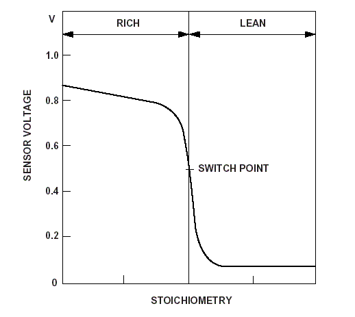
HO2S (Hot Oxygen) sensors develop a voltage by comparing oxygen in the atmosphere to the level of oxygen in the exhaust gas. Rather like a battery, the sensor produces a voltage between 0.1 volt and 0.9 volt depending on the amount of Hot Oxygen to which it is exposed in the exhaust stream. In Lean conditions (High in Oxygen, low fuel level) the sensor returns a low voltage because there is less differential between the oxygen in atmosphere, while in Rich conditions, (Low Oxygen, high fuel) it reads high because there is a large differential between the level of oxygen in the exhaust stream and atmosphere. The change between the two readings occurs suddenly in what is known as a 'switch', but this term does not have any electrical connotation. This effect is illustrated in the figure below:
Note that the sensor 'switches' suddenly, depending on the stoichometry of the exhaust gas. The sensor is not measuring the Lamda of the exhaust, but only whether it is Rich or Lean of oxygen - and so the term 'Lamda Sensor' is a misnomer. Its correct name is Heated Oxygen sensor, abbreviated in OBD to HO2S. (the previous term used in OBD I was HEGO, Heated Exhaust Gas Oxygen). The Ford sensors are exactly the same, front and rear, but they have a different colour and connection fitting for warranty purposes. The Front sensors have now been deleted from the Catalogue: only rear sensors are available, which means that new sensors when purchased from a Ford Main Dealer must have the old wiring soldered to the new. Monitor Conditions
The HO2S monitor consists of a number of tests. _____________________________________________ FRONT SENSOR SIGNAL Where Lack of Switch DTCs are recorded the LT Fuel Trims should be watched closely - if these show well into the negative or positive at idle they could be caused by an air inlet leak or a faulty Fuel Pressure Regulator - meaning that the fuelling has not changed rather than the HO2S not detecting it. Before changing front HO2S sensors Pressure Sensor and Sample Scan first - particularly if there are any starting issues. DTCs P1130 - Lack of Switching - Fuel Trim at Clip (no further trim available) Bank 1 P1131 - Lack of Switching - Sensor Indicates Lean, Bank 1 P1132 - Lack of Switching - Sensor Indicates Rich, Bank 1 P1150 - Lack of Switching - Fuel Trim at Clip, Bank 2 P1151 - Lack of Switching - Sensor Indicates Lean, Bank 2 P1152 - Lack of Switching - Sensor Indicates Rich, Bank 2 NOTE In extreme cases where the Front sensor(s) is not switching the Closed Loop operation is never achieved - the system stays on Open Loop fuelling and the DATA page on the Vehicle Explorer will show this. LOOP at PID# 1103 b6 on the Enhanced Data will show OPEN. Sensors OK
Entry Conditions ________________________________________ FRONT SENSOR FUNCTION The test is carried out once per drive cycle and lasts approx 6 seconds. P0133 Slow Response, Sensor, Bank 1 P0135 Slow Response, Sensor, Bank 2 These tend to show that the HO2S sensors may be failing, and may often be associated with the Lack of Switch DTCs P0131/0132 and P0151/0152. Confusingly, this DTC can be shown as HO2S Circuit Slow Response - but the test refers to the sensor, not the circuit. Sensors OK
________________________________________________ REAR SENSOR FUNCTION P0136 No activity Bank 1 P0156 No activity Bank 2 Typical voltage thresholds are Rich <0.25 to 0.50 volts and Lean >0.40 to 0.65 volts. _________________________________________ HO2S HEATER OPERATION The heater circuit current is tested by a separate circuit, and is sampled three times to guard against noise in the circuit. If two of these samples are below a threshold then the HO2S heater is deemed to have degraded. This test is carried out once per drive cycle. DTCs P0141 HO2S12 Heater Malfunction, Bank 1 P0155 HO2S21 Heater Malfunction, Bank 2 P0161 HO2S22 Heater Malfunction, Bank 2 ______________________________________________________ CHARACTERISTIC SHIFT DOWN (CSD) __________________________________________ The HO2S Sensor
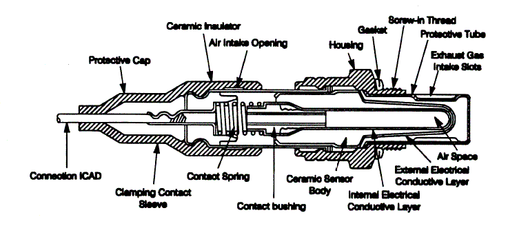
Above, a three-wire HO2S sensor. The 4-wire sensor has the addition of a dedicated case ground to the PCM. On the atmospheric side of the sensor an air intake opening provides the sample of atmosphere, which the sensor compares with exhaust gas from the Exhaust Gas Intake slots. This provides the reference voltage for the PCM. Below, details of the sensor.
_____________________________________________________ TROUBLESHOOTING If a careful inspection of the wiring raises no concern log on to the PCM and take a reading of the sensors after warming the engine for at least 3 minutes (to allow closed loop to commence.) Several points should be borne in mind:
Heater Circuit Malfunction
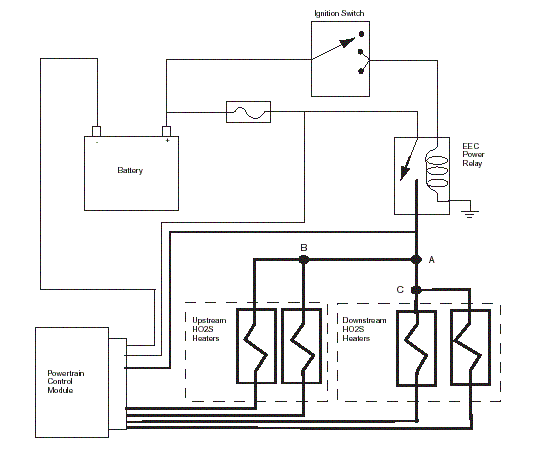
Splice A provides the power for both upstream and downstream sensors. A wiring problem with this splice will produce the DTCs P0135/ P0155, P0141/P0161 together, (only 2 of those for four cylinder engines of course.) Splice B provides the power to the Upstream (front) sensor(s) and generates the DTC P0135/P0155 Splice C provides the power to the downstream sensor(s) and will produce the DTC P0141/P0161 _______________________________________________________ OBOTO SYNDROME Keith had run his first OBD check with the Vehicle Explorer software on his 24V, which revealed that on one Bank the sensors were not switching at all - they were flatlined. This should mean that the sensors had failed, but curiously, when the sensors were changed for new ones the engine ran even worse. When the other Bank sensors were disconnected those flatlining sensors immediately started working perfectly. The engine ran badly with both banks connected, but as soon as one bank sensors were unplugged the car ran smoothly. This was a puzzle - and there is nothing about such a symptom in the manuals. Eventually the Keith found the cause - the fuel INJectors had been reconnected wrongly on work carried out on the cylinder head before he had bought it. For information, the Injector connections are as follows:
INJECTOR CABLE connects to
INJECTOR
1 1
2
6
3
5
4
4
5
3
6 2
Once the wiring to the INJectors had been corrected the engine ran well and the OBD cycle was restored. One can only conjecture that the PCM detected that the Banks were switching mixture wrongly and would only maintain close-loop on one Bank at a time. ____________________________________________________ DRIVEABILITY
CONCERNS
____________________________________________________ Changing the HO2S Sensor The new sensor is fitted in place and tightened to a torque of 42Nm. The wiring should be re-clipped carefully to prevent it from chafing. Diagrams © Ford (Europe) EricR |
||||||||||||||||||||||||||||||||||||||||||||||||||||||||||||||||
|
|
|
Copyright © 2003 www.fordscorpio.co.uk |
|
||||||||||||||||||||||||||||||||||||||||||||||||||||||||||||||